Managing Real-Time Data Acquisition
Once the project has been created, the appropriate device is selected, and the connection has been established and verified, it is possible to configure and start a Real-Time Data Acquisition (RT-DAQ) session.
RT-DAQ Configuration
In order to configure RT-DAQ, invoke Configure RT-DAQ command. This command can be invoked in two different ways. First, it is possible to access it from the Project Explorer, by right clicking on the item representing the device and choosing the appropriate command. Second, it is possible to select Configure RT-DAQ command from the Ribbon Menu of the Main Window.
The difference between the two options is noticeable only when there are more than one selected device. By invoking the command from the project explorer, it is possible to configure RT-DAQ on one particular device. On the other hand, by invoking the Configure RT-DAQ command from the Ribbon, one attempts to configure all devices at once.
Once the command is invoked, the following Configure RT-DAQ Dialog is prompted to the user enabling configuration of the RT-DAQ session on the actual device.
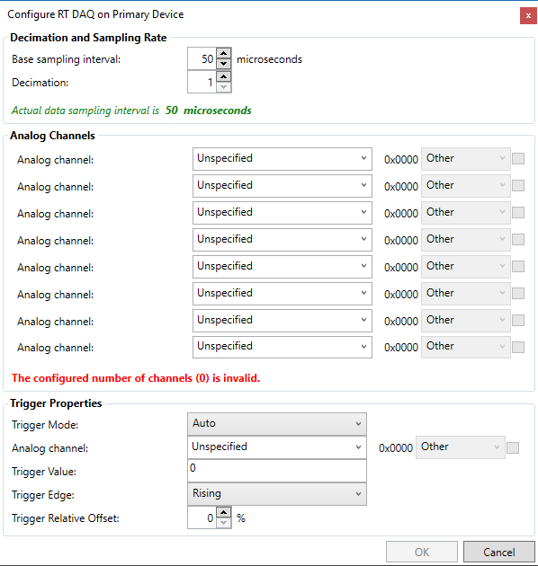
Configure RT-DAQ Dialog with all properties at their default values.
The Configure RT-DAQ Dialog enables configuration of the following parameters:
Decimation and Sampling Rate * Sampling rate specifies the base inter-sampling interval, which is governed by the underlying
LARA-100hardware. It is important for the value specified here to be equal to the sampling rate configured in the actual hardware. If this is not so, the plotting of signals and spectra, filtering and other signal processing functionality may not work correctly. * Decimation is an integer number specifying which basically specifies the downsampling rate with respect to the sampling rate specified above. The actual intersampling interval of signals coming from the LARA-100 device will besampling_rate * decimation. The information regarding the actual sampling rate is indicated in green at the bottom of the Decimation and Sampling Rate group.Analog Channels are variables from the underlying
DSPcode that will be acquired during aRT-DAQsession. For each variable, it is important to select the type which can be either Singe or Integer32 (it must not be Other which is the default value). Before a type is selected, a box must be checked which enables type selection. The allowable number of selected channels are 1, 2, 3, 4, 6 and 8. It is not possible to specify 5 or 7 channels. If an invalid number of channels is selected, if some of the selected channels do not have specified type, or if some of the selected channels are invalid an appropriate error will be indicated below the Analog Channels group. In this case, it will not be possible to confirm the configuration, since theOKbutton will be disabled.Trigger Properties enable one to define trigger-related properties. * Two trigger modes are supported: Auto (the default) and Normal. In the Auto mode triggering is disabled, and new data will be received as soon as they are available on the device. In the Normal mode, new data will be sent only if trigger condition is satisfied. * Trigger Source is the variable for which the trigger condition is evaluated. Trigger source may or may not be included in the analogue channels which are configured for RT-DAQ. * Trigger is activated once the source signal passes the trigger value, either from above to below (falling edge trigger), or from below to above (raising edge trigger). * Relative offset can also be specified, designating relative offset between a triggering instant and first transmitted sample.
Once the configuration is specified. The dialog will indicate what will be the length of each individual channel, both in sampling instants and in absolute time. This is important because the total number of values transmitted at every RT-DAQ frame is constant, equal to 4080 samples. This number is evenly distributed among each of the configured channels (explaining also why 5 and 7 are invalid number of channels).
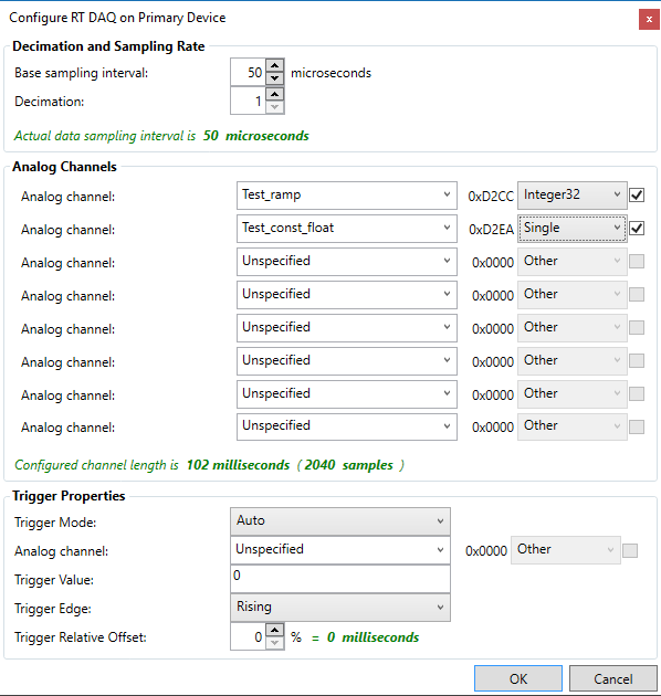
Configure RT-DAQ Dialog with first two analog channels configured for RT-DAQ.
By pressing OK, the RT-DAQ session is successfully configured. This can be seen in several ways. First, the RT-DAQ status is changed, which is indicated in the Diagnostics Pane. Second, the Start RT-DAQ command is enabled in the Ribbon Menu of the Main Window.
Starting RT-DQ session
As always, there are two ways to start an RT-DAQ session. The first one is by right clicking on the name of the device in the Project Explorer, and then selecting the Start RT-DAQ Command from the drop-down menu. Alternatively, one can choose Start RT-DAQ from the Ribbon Menu of the Main Window.
Once the session has been started, one can see the change in the selected analog channels by opening a Signal Scope, for example, and dragging the desired channel from the Project Explorer.
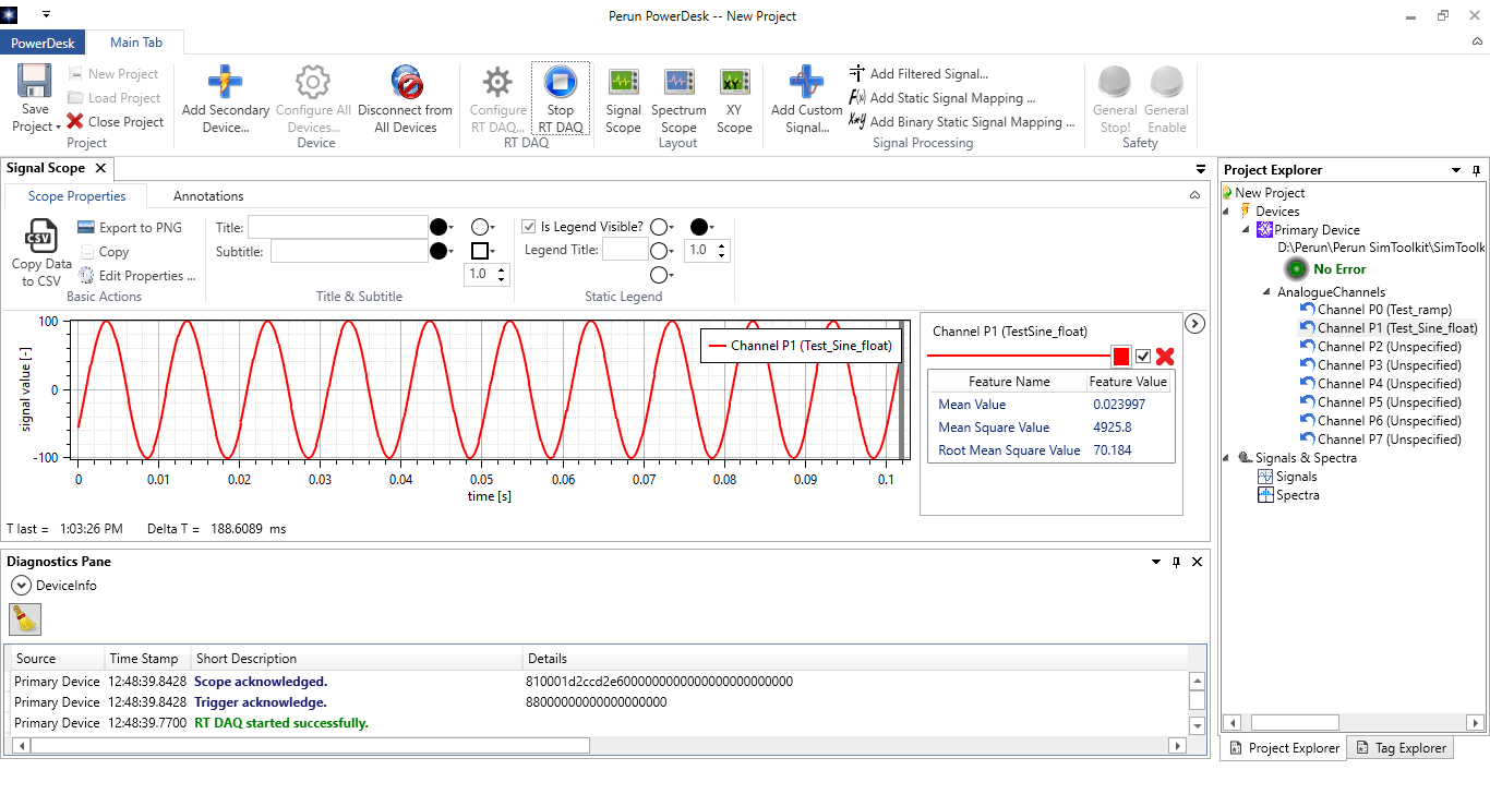
Main Window with a Signal Scope showing one of the channels selected for RT-DAQ. Channel values are constantly updated, which can be verified either by noticing changes in the data, or by inspecting the Scope Status Bar.
Note that once the scope is started, the cyclic poling of the Flags_Perun variable is not stopped. This is because the Flags_Perun is actually transmitted with every scope frame. Therefore, all error messages are regularly sent to the application and it remains responsive to any device-related errors.
Stopping RT-DAQ session
The RT-DAQ session can be stopped in the two usual ways. Note that once the session has been initiated, the Start RT-DAQ command in the Main Ribbon is replaced by the Stop RT-DAQ command.
Changing RT-DAQ configuration
RT-DAQ configuration can not be changed during an RT-DAQ session is active. In order to change the configured analog channels, decimation or trigger settings, it is necessary to first stop RT-DAQ, reconfigure and then start it again.